4.9 KiB
Protectli Vault FW2B and FW4B
This page describes how to run coreboot on the Protectli FW2B and Protectli FW4B.
Required proprietary blobs
To build a minimal working coreboot image some blobs are required (assuming only the BIOS region is being modified).
+-----------------+---------------------------------+---------------------+
| Binary file     | Apply                           | Required / Optional |
+=================+=================================+=====================+
| FSP             | Intel Firmware Support Package  | Required            |
+-----------------+---------------------------------+---------------------+
| microcode       | CPU microcode                   | Required            |
+-----------------+---------------------------------+---------------------+
| vgabios         | VGA Option ROM                  | Optional            |
+-----------------+---------------------------------+---------------------+
FSP is automatically added by coreboot build system into the image) from the
3rdparty/fsp submodule.
microcode updates are automatically included into the coreboot image by build
system from the 3rdparty/intel-microcode submodule.
VGA Option ROM is not required to boot, but if one needs graphics in pre-OS stage, it should be included.
Flashing coreboot
Internal programming
The main SPI flash can be accessed using flashrom.
External programming
The system has an internal flash chip which is a 8 MiB soldered SOIC-8 chip. This chip is located on the bottom side of the case (the radiator side). One has to remove all screws (in order): 4 top cover screws, 4 side cover screws (one side is enough), 4 mainboard screws, 3 CPU screws (under the DIMM). Lift up the mainboard and turn around it. The flash chip is near the mainboard edge close to the Ethernet Controllers. Use a clip (or solder the wires) to program the chip. Watch out on the voltage, the SPI operates at 1.8V! Specifically, it's a Macronix MX25U6435F (1.8V) - datasheet.
Known issues
- After flashing with external programmer the board will not boot if flashed the BIOS region only. For some reason it is required to flash whole image along with TXE region.
- USB 3.0 ports get detected very late in SeaBIOS, it needs huge timeout values in order to get the devices detected.
Untested
Not all mainboard's peripherals and functions were tested because of lack of the cables or not being populated on the board case.
- internal USB 2.0 header
Working
-
USB 3.0 front ports (SeaBIOS and Linux)
-
4 Ethernet ports (2 Ethernet ports on FW2B)
-
2 HDMI ports with VGA Option ROM
-
2 HDMI ports with libgfxinit
-
flashrom
-
PCIe WiFi
-
SATA and mSATA
-
Super I/O serial port 0 (RS232 via front RJ45 connector)
-
SMBus (reading SPD from DIMMs)
-
initialization with Braswell FSP
-
SeaBIOS payload (version rel-1.13.0)
-
booting Debian, Ubuntu, FreeBSD
Not working
- mPCIe debug card connected to mSATA (mSATA slot has LPC signals routed, however for some reason the debug card is not powered)
Technology
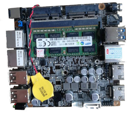
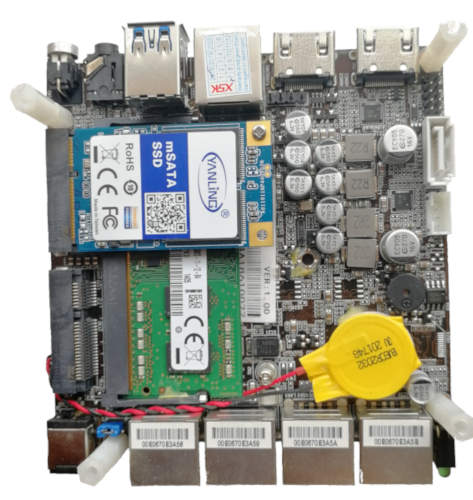
The mainboard has two variants: FW2B and FW4B. They have different Braswell SoC. The FW2B replaces 2 out of 4 Ethernet Controllers with 4 USB ports connected via FE1.1 USB 2.0 hub.
- FW2B:
+------------------+--------------------------------------------------+
| CPU              | Intel Celeron J3060                              |
+------------------+--------------------------------------------------+
| PCH              | Braswell                                         |
+------------------+--------------------------------------------------+
| Super I/O        | ITE IT8613E                                      |
+------------------+--------------------------------------------------+
| Coprocessor      | Intel Trusted Execution Engine                   |
+------------------+--------------------------------------------------+
- FW4B:
+------------------+--------------------------------------------------+
| CPU              | Intel Celeron J3160                              |
+------------------+--------------------------------------------------+
| PCH              | Braswell                                         |
+------------------+--------------------------------------------------+
| Super I/O        | ITE IT8613E                                      |
+------------------+--------------------------------------------------+
| Coprocessor      | Intel Trusted Execution Engine                   |
+------------------+--------------------------------------------------+

